
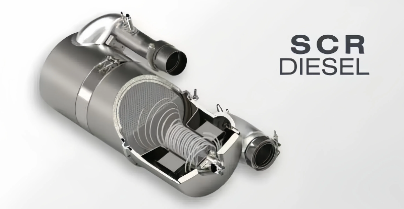
SCR (Selective Catalytic Reduction) components are the core parts of diesel engine exhaust treatment systems, mainly used to reduce nitrogen oxide (NOx) emissions in exhaust gas, meeting National IV and above emission standards. They are widely applied in diesel-powered equipment such as commercial vehicles, construction machinery, and ships. Unlike SCR components in ordinary power electronics, SCR components in diesel engine exhaust treatment systems operate in an environment of high temperature, high dust, and corrosive exhaust gas for a long time, which are prone to problems such as catalyst deactivation, abnormal urea injection, exhaust blockage, and sensor failure. These problems directly lead to decreased engine power, increased fuel consumption, illuminated fault lights, and even failure to start normally. Timely and standardized maintenance is the key to ensuring that diesel engine exhaust emissions meet standards and the equipment operates stably. This article provides comprehensive and practical guidance for maintenance personnel from five aspects: basic understanding of SCR components, common fault diagnosis, standardized maintenance procedures, post-maintenance inspection, and safety precautions.
I. Basic Understanding of SCR Components in Diesel Engine Exhaust Treatment
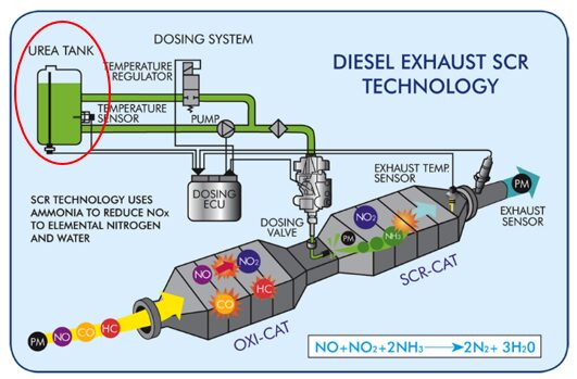
Before carrying out maintenance work, it is necessary to clarify the core structure and working principle of SCR components in diesel engine exhaust treatment systems to avoid maintenance errors caused by cognitive deviations. The diesel engine SCR exhaust treatment system is mainly composed of an SCR catalyst (core component), a urea injection system, an exhaust gas temperature sensor, a nitrogen oxide sensor, a urea tank, and a urea pump. Among them, the SCR catalyst is the core, filled with special catalysts (commonly vanadium-based and copper-based catalysts). The urea aqueous solution (automotive urea) injected through the urea injection system decomposes into ammonia (NH₃) at high temperatures. Ammonia reacts with nitrogen oxides in the exhaust gas under the action of the catalyst through a selective reduction reaction, converting NOx into harmless nitrogen (N₂) and water (H₂O) to achieve exhaust gas purification.
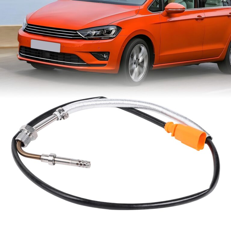
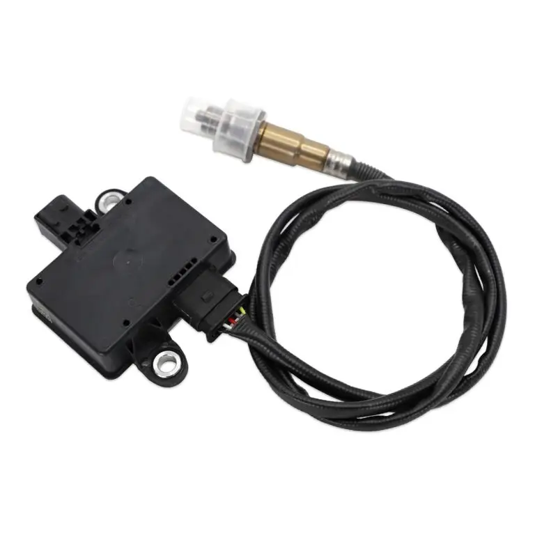
Core components and functions of the SCR assembly: First, the SCR catalyst, whose core is a catalyst carrier (honeycomb ceramic carrier) coated with a catalyst on the surface. It is the main site for NOx reduction reactions, and the smoothness of the carrier and the activity of the catalyst directly determine the purification effect. Second, the urea injection system, including the urea pump, urea nozzle, and urea pipeline, is responsible for accurately injecting the urea aqueous solution into the exhaust pipeline to mix with the exhaust gas. Third, the sensor assembly: the exhaust gas temperature sensor monitors the exhaust gas temperature (ensuring the operating temperature of 200-400℃ required for the reaction), and the nitrogen oxide sensor monitors the NOx concentration at the inlet and outlet, feeds back the purification effect, and provides adjustment signals for the ECU (Engine Control Unit). Fourth, auxiliary components: the urea tank is used to store automotive urea, and the urea filter is used to filter impurities in the urea to avoid clogging the nozzle and catalyst.
II. Common Faults and Diagnostic Methods of SCR Components
Faults of SCR components in diesel engine exhaust treatment are mostly related to catalyst aging, abnormal urea supply, exhaust blockage, sensor failure, and exhaust gas impurity accumulation. Different fault performances correspond to different diagnostic ideas. Combined with the engine fault light prompt and equipment operation status, the problem can be quickly located. The following are the 5 most common faults and practical diagnostic methods.
(I) Classification and Performance of Common Faults
- Catalyst Deactivation or Aging: This is the most common type of fault, divided into chemical deactivation and thermal deactivation. Chemical deactivation is mostly caused by sulfur and phosphorus in diesel oil or impurities in inferior urea leading to catalyst poisoning; thermal deactivation is caused by excessive exhaust gas temperature (exceeding 600℃) leading to catalyst sintering. Fault performance includes illuminated engine fault light, excessive exhaust emissions, decreased power, increased fuel consumption, the NOx sensor feeding back that the outlet NOx concentration is close to the inlet concentration, and the ECU reporting a “low catalyst efficiency” fault code.
- Urea Injection System Fault: Including urea pump damage, urea nozzle clogging, urea pipeline leakage or clogging, and abnormal urea pressure. Fault performance includes abnormal urea consumption (sudden increase, sudden decrease, or no consumption), insufficient engine power, illuminated fault light, the ECU reporting fault codes such as “abnormal urea injection”, “low/high urea pressure”, and “nozzle clogging”. In severe cases, it will cause crystallization and clogging of the SCR catalyst.
- Exhaust Blockage: Mostly caused by carbon deposition on the catalyst carrier, urea crystallization, and dust accumulation in the exhaust gas, divided into partial blockage and complete blockage. Fault performance includes increased engine exhaust resistance, significant power reduction, unstable idling, abnormally high exhaust temperature, and even engine failure to start in severe cases. Blockage traces on the carrier can be seen by disassembling both ends of the catalyst.
- Sensor Fault: Failure or abnormal signal of the exhaust gas temperature sensor and nitrogen oxide sensor. A fault in the exhaust gas temperature sensor will cause the ECU to be unable to judge the reaction temperature, leading to abnormal urea injection; a fault in the nitrogen oxide sensor will cause the ECU to be unable to monitor the purification effect, resulting in false faults or inability to adjust the urea injection volume. Fault performance includes illuminated fault light, disordered urea injection, decreased power, and the ECU reporting fault codes such as “abnormal sensor signal” and “sensor open circuit/short circuit”.
- Substandard or Insufficient Urea Supply: Use of inferior urea, inconsistent urea concentration (standard is 32.5%), or insufficient urea in the urea tank, clogged urea filter. Fault performance includes catalyst crystallization, reduced purification effect, illuminated fault light, and the ECU reporting fault codes such as “abnormal urea quality” and “low urea level”. Long-term use will lead to permanent damage to the catalyst.
(II) Practical Diagnostic Methods
Safety preparations before diagnosis: Turn off the engine, wait for the engine to cool down (the exhaust system temperature is high to avoid scalding), disconnect the vehicle’s main power supply, wear high-temperature resistant gloves and protective goggles, and use special maintenance tools to avoid component damage or personal injury.
- Fault Code Reading: Use a special diesel engine diagnostic instrument (such as Bosch, Cummins diagnostic instrument) to connect to the vehicle’s OBD interface, read the fault codes stored in the ECU, and initially locate the fault type (such as catalyst fault, urea injection fault, sensor fault) combined with the fault code description. This is the fastest diagnostic method.
- Visual Inspection: Observe whether the SCR catalyst shell is damaged, deformed, cracked, or has smoke leakage traces; check whether the urea tank level is sufficient, whether the urea pipeline is leaking, aging, or bent, whether the urea nozzle is crystallized or clogged, whether the sensor wiring is loose, oxidized, or disconnected, and whether the exhaust pipeline is dusty or leaking.
- Urea System Inspection: Start the engine, wait for the water temperature and exhaust temperature to reach the normal operating range (exhaust temperature ≥ 200℃), use a diagnostic instrument to monitor the urea pump pressure (normal range 0.8-1.2MPa) and urea injection volume, and observe whether the urea nozzle injects normally; if urea does not inject, check whether the urea pump is working, whether the urea filter is clogged, and whether the nozzle is crystallized. The nozzle can be disassembled for cleaning or testing.
- Sensor Inspection: Use a multimeter to measure the resistance of the exhaust gas temperature sensor, and judge whether the sensor is normal according to the temperature change (resistance increases with temperature rise); measure the supply voltage and signal voltage of the nitrogen oxide sensor, compare with the standard value to judge whether the sensor is invalid. If the signal is abnormal, check the sensor wiring or replace the sensor.
- Catalyst Inspection: First, observe the catalyst carrier. Disassemble the flanges at both ends of the catalyst to check whether the carrier is unobstructed, has carbon deposition, crystallization, or damage. If the carrier is severely clogged, it needs to be cleaned or replaced; second, use a diagnostic instrument to compare the NOx concentration at the inlet and outlet of the catalyst. If the outlet concentration is close to the inlet concentration, it indicates that the catalyst is deactivated and needs to be replaced.
III. Standardized Maintenance Procedures for SCR Components
Maintenance should follow the principle of “first read the code, then diagnose, then disassemble, replace/repair, and finally inspect”. Combined with the particularity of the diesel engine exhaust treatment system, the steps are clear and the operation is standardized to avoid secondary damage to components or the engine. The specific procedures are as follows:
(I) Preparations
- Tool Preparation: Special diesel engine diagnostic instrument, high-temperature resistant gloves, protective goggles, wrenches (socket, box-end), screwdrivers, urea nozzle cleaning tools, catalyst cleaning equipment, compressed air, oil suction pot, multimeter, wires, insulating tape.
- Accessory Preparation: According to the fault diagnosis results, prepare matching models of SCR catalysts, urea pumps, urea nozzles, exhaust gas temperature sensors, nitrogen oxide sensors, automotive urea (32.5% standard concentration), urea filters, gaskets and other accessories. Ensure that the accessory model matches the engine model and exhaust treatment system to avoid fault recurrence caused by inconsistent specifications.
- Safety Preparation: Turn off the engine, wait for the exhaust system and engine to cool down completely (at least 30 minutes), disconnect the vehicle’s main power supply, clean the work area to avoid debris entering the exhaust pipeline or urea system, and wear high-temperature resistant and corrosion-resistant protective equipment.
(II) Component Disassembly
- Mark Wires and Pipelines: Before disassembly, use a marker to mark the connection positions of sensor wires and urea pipelines to avoid incorrect wiring and pipe connection later, and record the installation direction of the catalyst (to avoid reverse installation, which affects the purification effect).
- Remove Sensors: Use a wrench to unscrew the exhaust gas temperature sensor and nitrogen oxide sensor, gently pull out the sensor plug, take good protection (avoid damage to the sensor probe and contamination by oil), and sort out the sensor wires.
- Remove the Urea Injection System: Disconnect the urea pump power supply and urea pipeline, use a wrench to unscrew the urea nozzle fixing bolts, take out the nozzle, remove the urea filter, plug the urea pipeline port (to avoid debris entering), and clean the residual urea in the pipeline with an oil suction pot.
- Remove the SCR Catalyst: Unscrew the fixing bolts of the flanges at both ends of the catalyst, gently take out the catalyst, be careful to avoid collision and falling (the ceramic carrier is fragile), and clean the gasket residue and carbon deposition on the flange surface.
(III) Replacement and Repair of Faulty Components
- Catalyst Repair and Replacement: If the catalyst carrier is slightly clogged or has carbon deposition, a special catalyst cleaning equipment can be used to clean the carrier through high-pressure air flow combined with cleaning agent to remove carbon deposition and crystallization; if the carrier is severely clogged, damaged, or the catalyst is deactivated (the NOx conversion efficiency detected by the diagnostic instrument is less than 80%), a new catalyst needs to be replaced. When replacing, ensure that the flange gasket is installed in place to avoid exhaust leakage.
- Urea Injection System Repair: When the urea nozzle is clogged, use a special cleaning tool (ultrasonic cleaning machine) to clean the nozzle to remove crystallization and test the nozzle injection effect. If the injection is uneven or cannot be injected, replace the nozzle; when the urea pump pressure is abnormal, check the internal wear of the pump body. If the wear is severe, replace the urea pump; when the urea pipeline is clogged, blow the pipeline with compressed air or replace the pipeline; when the urea filter is clogged, directly replace it with a new one.
- Sensor Replacement: If the exhaust gas temperature sensor and nitrogen oxide sensor are invalid, replace them with matching models. During installation, ensure that the probe is clean and the wiring is firm to avoid poor contact. After replacement, calibrate with a diagnostic instrument.
- Urea System Cleaning and Filling: Clean the impurities inside the urea tank, replace with new automotive urea (32.5% standard concentration), and it is strictly prohibited to use inferior urea or tap water for dilution; check the urea tank vent to ensure it is unobstructed to avoid negative pressure in the urea tank affecting urea supply.
- Exhaust Pipeline Cleaning: Clean the carbon deposition and dust in the exhaust pipeline at both ends of the catalyst, check whether the exhaust pipeline is damaged or leaking. If there is damage, perform welding repair or replace the pipeline to ensure smooth exhaust and no leakage.
(IV) Component Assembly
- Install the SCR Catalyst: Align the new or cleaned catalyst with the flange position, install the gasket, and evenly tighten the flange fixing bolts with moderate force to avoid exhaust leakage caused by poor sealing.
- Install the Urea Injection System: Install the cleaned or new urea nozzle in place, tighten the fixing bolts, connect the urea pipeline to ensure no leakage; install the urea filter and urea pump, connect the urea pump power supply and pipeline, and check the pipeline direction to avoid bending.
- Install Sensors: Install the exhaust gas temperature sensor and nitrogen oxide sensor in place, tighten the fixing bolts, connect the sensor plug to ensure correct and firm wiring, sort out the wires, and avoid contact with high-temperature components.
- Comprehensive Inspection: Check whether all components are installed firmly, whether the pipelines and wires are connected correctly without looseness or leakage; clean the work area to ensure no debris remains, and the urea level in the urea tank is sufficient.
IV. Post-Maintenance Inspection and Debugging
After maintenance, strict inspection and debugging are required to ensure that the SCR components work normally, exhaust emissions meet standards, and avoid fault recurrence. The inspection steps are as follows:
- Static Inspection: Use a diagnostic instrument to clear the fault codes in the ECU, check whether the signals of each sensor are normal, whether the urea pump pressure is within the standard range, and whether the urea nozzle injects normally; check whether each pipeline and flange has leakage, whether the catalyst is installed firmly, and whether the sensor wiring is good.
- Idle Test: Start the engine, run at idle speed for 5-10 minutes, observe the engine operation status, check whether the urea pump works normally, whether the urea nozzle injects normally, whether the exhaust temperature rises gradually (reaching above 200℃), and whether the fault light goes out.
- Load Test: Raise the engine to medium and high speed (simulate actual working conditions), run for 30-60 minutes, use a diagnostic instrument to monitor the NOx concentration at the inlet and outlet of the catalyst to ensure the conversion efficiency ≥ 80%; observe the urea consumption (normal consumption rate matches the engine load), check whether the exhaust temperature and power output are normal, and there is no abnormal noise or leakage.
- Exhaust Gas Detection: Use an exhaust gas detector to detect the NOx concentration in the engine exhaust gas to ensure it meets National IV and above emission standards; if the emission does not meet the standards, recheck components such as the catalyst, urea injection system, and sensors until the detection is qualified.
If an abnormality occurs during the inspection, turn off the engine immediately and recheck the fault. Focus on checking the catalyst installation direction, urea injection volume, and sensor signals until the inspection is qualified, to avoid engine damage or excessive emissions caused by improper maintenance.
V. Safety Precautions for Maintenance
The maintenance of SCR components in diesel engine exhaust treatment involves high temperature, high pressure, and chemical reagents (automotive urea). Improper operation during maintenance may easily lead to risks such as scalding, component damage, and chemical corrosion. The following safety precautions must be strictly followed:
- Cooling Operation: Before maintenance, the engine must be turned off, and the exhaust system and engine must be allowed to cool down completely (at least 30 minutes). It is strictly prohibited to disassemble components at high temperature to avoid scalding.
- Protective Measures: Wear high-temperature resistant gloves, protective goggles, and corrosion-resistant gloves to avoid direct contact with high-temperature components and automotive urea, preventing scalding and chemical corrosion; keep the work area ventilated to avoid accumulation of urea vapor.
- Power Off Operation: Before disassembling electrical components such as sensors and urea pumps, the vehicle’s main power supply must be disconnected to avoid short circuits, damage to electrical components, or safety accidents.
- Component Protection: When disassembling the catalyst, avoid collision and falling to prevent the ceramic carrier from breaking; the sensor probe should avoid being contaminated with oil and debris to prevent abnormal signals; after disassembling the urea pipeline and nozzle, plug the port in time to avoid debris entering.
- Reagent Use: Strictly use automotive urea with a standard concentration of 32.5%. It is strictly prohibited to use inferior urea, tap water, or other reagents instead, to avoid damaging the catalyst and urea injection system; if urea leaks, clean it in time to avoid corrosion of the ground and components.
- Operation Specifications: When installing the catalyst, ensure the correct installation direction and the flange gasket is installed in place to avoid exhaust leakage; when tightening bolts, apply uniform force to avoid component deformation; after maintenance, inspection must be carried out to ensure no faults before putting into use.


Your article is excellent. It has a clear structure, accurate professional terminology, and comprehensive and practical content, which can effectively guide maintenance personnel in the maintenance work of SCR components in diesel engine exhaust treatment systems.